Final Product
Single Modular Bin

Multiple Modular Bins

What Did We Learn?
- Heat set inserts work great, but they scare me
- Buying a heat set insert extraction tip may not be worth it
- Brass is soft
- Adding a pin/slot feature was nice for installation to account for "play", but there are ways to achieve better alignment
- Dovetail joints are cheap to add for 3D printing
- When three legs is enough and when it isn't
- How to recover from a clog
How It Works
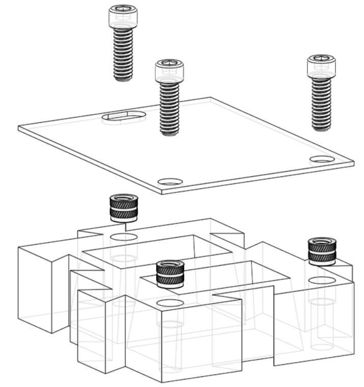
This design is straightforward. I have two plastic parts which I joined together by using heat set inserts and socket head cap screws. Below is an exploded view of the assembly.

Once fastened, the assembly is flipped over exposing the opening for the bins and allowing the socket head cap screw heads to act as feet.
 If more bins are needed, the exact same assembly can be printed, fastened together, and then joined via the dovetail joints.

Once fastened, the assembly is flipped over exposing the opening for the bins and allowing the socket head cap screw heads to act as feet.


How It Was Made
Design
The bin base was sketched so that there was enough material on the outer flanges to make dovetail and hole cuts. The material between the bins was made thinner since no cuts were to be made on that surface. The outer dimensions of the sketch are roughly 3:4. Typically I go to the golden ratio (1:1.618) when sizing rectangles to be more visually appealing; however, the build volume of my printer was not cooperating so the height to width ratio is off.
 I had to be judicious with my build height since the part height has an impact on how long it takes to print the part. A 1" extrusion seemed like a good balance between functionality and print time. The drafts help funnel parts within the bin towards the center of the bin cutout.
 The dovetail cutouts were interesting to design. I found through trial and error that under-sizing the male dovetail width, increasing the male dovetail height, and increasing the approach angle (i.e., from 60 degrees to 65 degrees) printed a successful mate between the two (although it turned out a little looser than I would prefer). I think next time I would keep the approach angles the same but optimize the clearances.
 Once the dovetail extrusions/cuts were made, the part was flipped over where counterbored blind holes were made. The counterbores were sized such that the heat set inserts could be positioned in the holes, and the remaining length of the blind holes was sized such that the diameter and length could accommodate the socket head cap screws.

 The base plate is just a plate 1/16" thick with two holes and a slot cutout. The two holes were slightly oversized by 1/32" diametrically so that the fastener can clear the hole while coming in contact with the head of the fastener. The cap screws are 1/4"-20 and 3/4" long. The head of the fastener has a diameter of 0.375", or 1.5 times the major diameter (it's always nice when something from school matches up with reality!). The slot was sized to two times the diameter of the fastener. The idea behind the slot was to accommodate for any misalignment that may have occurred during assembly. Three fasteners were chosen so that the assembly would sit level - since the fasteners act as feet for the assembly.


And... here's a render!

Print(s)
Both parts we printed using PLA, 100% infill, 0.30625 mm layer height, and running the extruder at 195 Celsius. The plastic prints can be downloaded from this link.


Bin Base

Base Plate

Assembly
The assembly of the parts began with the bin base in the orientation shown below:
 Next the heat inserts were positioned into the counterbores.
 Everything is now staged for the fun part!
 How this works is you heat up the installation tip to a temperature above the PLA melting point via a soldering iron.
 This installation tip is used to "ream" the heat set insert into the plastic. Once the desired depth is achieved, the soldering iron is removed and the knurls on the heat set insert grip the plastic as the plastic cools around the heat set insert.

 Now that the inserts are set the base plate can be fastened to the base bin.


More On What We Learned
Heat Set Inserts and Extraction/Insertion Tips
The insertion tip is a must have if you plan on using heat set inserts. Make sure you get the correct tip size. I got the extraction tip as well. It is nice knowing that if I mess up a set that I can salvage the insert; however, if you mess up the set you probably can't save the plastic part.
I had an incredibly satisfying feeling when the inserts were installed correctly the first time. I couldn't help but think about how any misalignment or reaming the insert too far could ruin my 6 plus hour build. On my next project I plan on exploring other joining methods.
Brass Is Soft
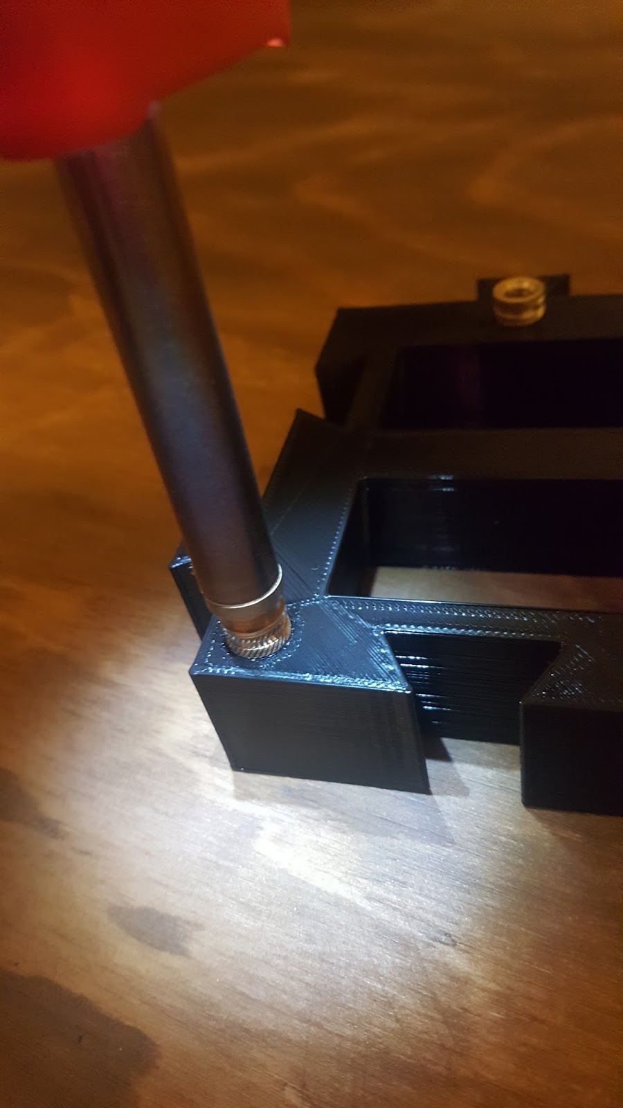
When installing the fasteners I noticed more torque was needed than initially. After backing the fastener in and out of the heat set insert a couple times the two parts mated with little torque. Why? Well I snapped this picture and from it figured that since brass is softer than steel, the brass insert conformed to the steel threads after a couple installs.
 Brass, like bronze, is a copper alloy; however, unlike bronze, brass is alloyed with zinc opposed to tin. Unlike the steel fastener used in this design, which is an interstitial alloy, brass is a substitutional alloy.

Generally speaking the higher the zinc content the higher strength of the alloy. If the content exceeds 50% zinc then the brass becomes brittle and is commonly referred to as white brass. The brass used in this design was probably common brass which is 37% zinc 63% copper or high brass which is 35% zinc 65% copper. Both can be cold worked which is what I think happened during the fastener install when the brass insert came in contact with the steel threads. On top of that the harder steel fastener stripped material from the insert hence the brass deposits shown on the fastener above.
Alignment Features
If you are performing multiple machining operations after your initial build where the stack up of tolerances matter, then the alignment of you parts matter. For this build there were only two parts stacking up, the bin base and the base plate. Because of that I elected to use two holes and slot to account for any play between aligning the two parts. Incorporating the slot made the assembly easier (marginally, it wasn't that bad to begin with). If I don't care much about alignment I tend to use slots opposed to holes; however, a diamond pin and a hole is a very good technique to use if aligning a part on a plane. Call it laziness or call it admiration for someone else's work; whichever, I recommend you check out this article at Misumi for more information (lots a great images!).
Dovetail Joints
Using dovetail joints are a nice way to limit another degree of freedom without adding more features to your part. In addition to this, depending on how you are building your part, a dovetail built at an angle may be the only way to build the joint (unless you are using supports).
My dovetails came in a bit loose. Next go around I would tighten them up. Below is what I altered the joints for the next bin prints.

Anything extra contributes to wobble. Three legs though is not always the best in terms of stability. The goal, when achieving stability, is to have all of the forces (including the center of gravity) within the area created by the feet as shown below.

Now to test that statement! Below is the bin base with feet installed (no base plate part included in assembly for this test) and myself applying a force to various positions on the face.

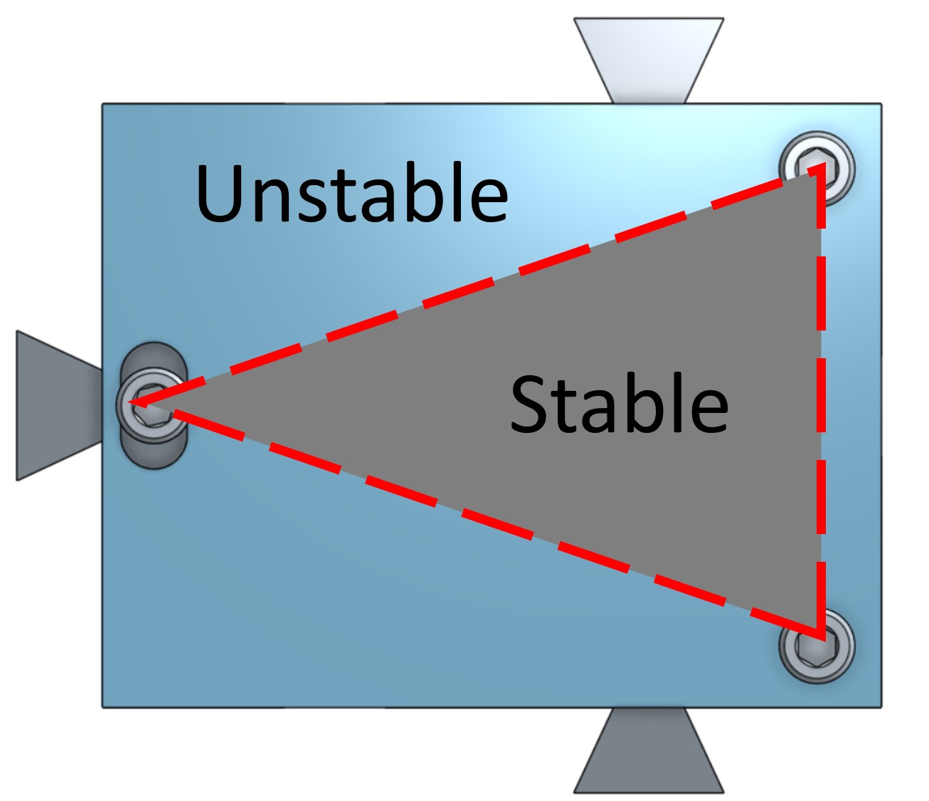
The following image shows different degrees of stability. Suppose the force can be applied to any point within the blue circle. Notice how the best stability is achieved if you can move your feet in such a way that the applied force is always within the inscribed shape.

Now look at this picture of my desk chair.

Whoever designed the chair took advantage of this principle by placing the feet outboard of where you sit so that the chair will not tilt regardless of where you sit down on the seat.
The takeaway here is that three legs should be used if you are concerned with eliminating wobble. Either increasing the number of legs and/or increasing the spacing between the legs will increase the stability of the system.
If you need both stability and to eliminate wobbling think about using adjustable or flexible feet.
One last note about tipping... the phenomena occurs when the CG of the component "crosses over" the pivot point. To explain this concept let's think about this in extremes. Suppose a fly lands on my part outside of the stability zone. We can all most likely intuitively agree that the fly will not tip the part, but how large of a force at the edge would it take to tip the part? What if the part was made of 304 SS? Tungsten? Below shows the free-body diagram and the results (from using statics).


My dovetails came in a bit loose. Next go around I would tighten them up. Below is what I altered the joints for the next bin prints.

When Three Legs Is Enough And When It Isn't
The general rule of thumb that I have been taught is that three legs is better than four legs. This is true if we are talking about reducing wobble in the system. The reason is that you only need three points to define a plane.Anything extra contributes to wobble. Three legs though is not always the best in terms of stability. The goal, when achieving stability, is to have all of the forces (including the center of gravity) within the area created by the feet as shown below.
Now to test that statement! Below is the bin base with feet installed (no base plate part included in assembly for this test) and myself applying a force to various positions on the face.

The following image shows different degrees of stability. Suppose the force can be applied to any point within the blue circle. Notice how the best stability is achieved if you can move your feet in such a way that the applied force is always within the inscribed shape.

Now look at this picture of my desk chair.

Whoever designed the chair took advantage of this principle by placing the feet outboard of where you sit so that the chair will not tilt regardless of where you sit down on the seat.
The takeaway here is that three legs should be used if you are concerned with eliminating wobble. Either increasing the number of legs and/or increasing the spacing between the legs will increase the stability of the system.
If you need both stability and to eliminate wobbling think about using adjustable or flexible feet.
One last note about tipping... the phenomena occurs when the CG of the component "crosses over" the pivot point. To explain this concept let's think about this in extremes. Suppose a fly lands on my part outside of the stability zone. We can all most likely intuitively agree that the fly will not tip the part, but how large of a force at the edge would it take to tip the part? What if the part was made of 304 SS? Tungsten? Below shows the free-body diagram and the results (from using statics).


The plot above shows the maximum force just before tipping as a function of the distance ratio. as you increase the weight of the part you also increase the maximum force at a specific ratio. So if you really need to up the stability, increase the number of supporting features to increase the stability zone area and increase the weight of the part (also move that CG lower!).
Recovering from a Clog
Oh dear.. mid-way through the print of the second base plate I noticed the build layer was really inconsistent. Even more concerning was that my printer was doing this:
 Time to open her up! The first step is to undo the springs which hold the fan onto the heat sink.
 Once you have both springs disengaged you should be able to see this:
 Once the top set screw is removed the guide tube can be pulled out of the extruder. As you can see below the filament got curled up in the extruder which was causing the jam.
 Using regular old scissors to cut the plastic freed up the jam.
 Success!


Make sure to install the fan back onto the heat sink properly. If you do not have the clip in the position shown below, the fan goes off center. I didn't think this would really matter much until the fan was sent crashing into my z-tower.
